OSPF ( Open Shortest Path First) - A detailed review and configuration .
Open Shortest Path First is a routing protocol which is using in bigger networks (mainly ISP's & Telecom networks) in now a days . It is based on link state advertisements and currently OSPF V2 is running which is developed in 1991 as per RFC 1247. The major advantages of OSPF are
1. Classless protocol
2.Supports VLSM (Variable Length Subnet Mask)
3.Using Multicast address to advertise link updates (224.0.0.4 - SPF routers & 224.0.0.5-DR routers )
4. Supports Plain text and MD5 authentication Mechanism
5. Works as per Dijkstra algorithm.
OSPF packet details
OSPF is using different types of packets for its communication, and the details are mentioned below
| OSPF Packet types | ||
| Type | Description | Functionality |
| 1 | Hello | To discover neighbors and selects DR&BDR* routers to exchange capabilitis |
| 2 | Database Description | To elect master/slave for router database exchange process to exchange the LSA headres |
| 3 | Link-State-Request | To request specefic LSA (Link State Advertisements ) |
| 4 | Link-State-Update | To send entire to the neighbor who requested the particular LSA through the LSR packet |
| 5 | Link-State-Acknowledge | To acknowledge and recept LSU packet |
(* DR- Designated Router is the router an OSPF area where all other router's will send their Link State Advertisements.
BDR- Backup Designated Router - This will take the responsibility of the DR if the DR is failed in an area)
Sample OSPF Packet
Sample OSPF Packet
| OSPF – Packet details | ||
| 32 bit | ||
| version | type | packet length |
| router ID | ||
| area ID | ||
| checksum | Autype | ||
| Authentication | ||
| Authentication | ||
A sample OSPF packet is 32 bit length and its details are given below
Version - This mainly indicates what version of the OSPF is running. Currently OSPF V2 is running.
Type- Indicates the OSPF packet type ( details are given above)
Packet Length- Total length of the OSPF packet
Router ID- This indicates ip address of the router . For cisco router highest ip address will take as the router ID. If loop back ip is configured highest loop back will take as router ID
Area ID- This filed checks the area of the packet belongs to. This is a 4 byte number and both routers should have same area ID to form neighbor relation ship.
Check Sum - This part will check the status of the entire OSPF packet.
Autype- Autype filed will check the respective authentication type configured for OSPF.
different Autypes are
1. 0 indicates no authentication
2. 1 indicates plain text authentication
3. 2 indicates MD5 authentication
Authentication - Indicates the authentication key for plain text authentication type.
Sample OSPF configuration

router 1 configuration


router 2 configuration


router 3 configuration
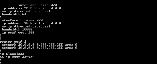

router 4 configuration

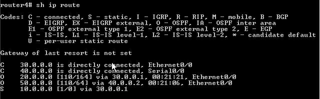
Testing the connectivity from work stations
PC1

PC2

OSPF Neighbor states
1. Down
This is the first stage of OSPF neighbor . If a neighbor is on down stage hello packet is not received from this particular neighbor, but packets can send to the neighbor .
2. Attempt
In this state router will send unicast hello packets to the neighbors in poll intervals . But as mentioned above these neighbors will not send hello packets in down state.
3. Init
Router will receive a valid hello packets from the neighbor, but receiving router id will not be added in the packets.
4. 2-way
This state indicates the bi directional communication between two neighbor routers .The router's will share each others router ID in hello packets and as per that it will decide, need to become neighbor with this router or not. In OSPF network DR/BDR selection will happen as per the 2 way link with the neighbors.
5. Exstart
Once the DR/BDR selection is happened router's will start exchanging information by creating a virtual link inside the network (like a master/slave). Router's with higher router ID will became the master .
6. Exchange
In this stage OSPF router's will exchange database descriptor (DBD) packets and this packet will contain LSA (Link State Advertisements) header's which will contain the details of entire LSA updates.
The contents of the DBD updates are cross checked with router LSA updates to make sure that information is passed to all neighbor's.
7.Loading
As per the DBD information and LSR (Link State Requests)router's will share the LSA , and this is the actual information share happening stage.
8. Full
This is the fully synchronized state with all the router's database is updated with proper LSA updates. This is the normal state of a OSPF router. If any of the router is not became full state , we can conclude that there will be an issue for forming adjacency .
Multi Area OSPF configuration
In larger networks we can find multiple area's in OSPF configuration than a single one . In multi area OSPF different kinds of router's are involved than single area OSPF
a. Internal router - Router involves in a single area
b. Back born router - Router where atleast one onterface is in area 0
c. Area Border Router (ABR) - Router attached to multiple areas
d. Autonomous System Boundary Router - At least one interface connected to another AS.
Sample multi area OSPF network

configurations is almost same except loop back configuration in MOSPF.
OSPF treats Loopback interfaces as STUB NETWORKS and advertise them as HOST ROUTES (with mask /32) regardless of their configured/native mask.According to RFC 2328, Host routes are considered to be subnets whose mask is "all ones (0xffffffff)". In this state, the router's interface is looped back to the network in hardware or software. In this state, the interface is unavailable for regular data traffic. However, it is still available for testing like ICMP pings and BERT. For this reason, IP packets may still be addressed to an interface in Loopback state. Such interfaces are advertised in router-LSA as single host routes, whose destination IP address is the interface address.
No comments:
Post a Comment